Servicing my Kawai K4 – replacing the push button switches

THIS IS AN ARCHIVED MIRROR SEE ORIGINAL AT drosera.f2s.com/Servicing_K4.htm
First let me highly recommend
MNX’s excellent K4 site
– it is a superb repository of masses of useful K4 stuff, so make sure you check it out!
A while ago I picked up an old K4 from Ebay for just over £100 which seemed quite reasonable at the time. I was looking for something that I could use as a master keyboard and decided on the K4 having owned a K4R in the past.
As with any Ebay purchase from a private individual there is always an element of risk, but I was pleased to find a pretty well looked after keyboard when I unpacked it.
It came with an underpowered replacement power supply that I replaced with an 800mA generic unit. After plugging in and switching on all seemed OK. I uploaded the factory patches and started dabbling. Everything worked—all the keys, the wheels, the sliders. The only annoyance was a couple of the buttons were not very responsive, but not so bad that I couldn’t live with them.
My first reaction to listening to it was just how different (and better) it all sounded when compared to the K4R module due to the effects that are only available on to the keyboard.
As time passed it was clear that some of the buttons needed to be sorted out as two of them had ceased working entirely. So as always ‘Google to the rescue’:- but I couldn’t find any definitive service instructions for the Kawai, just general repair notes or horrendous details of problems with other synths. Problems changing batteries, switches, buttons and other components along with corrosion caused by leaking electrolytic capacitors. So I was prepared for the worst!
So with some trepidation I metaphorically ‘girded up my loins’ and decided to see what I could manage in the way of repairs.
First I laid some towels on the table to protect both the table and synth and then put the keyboard base upwards on the towels. A quick perusal showed 22 screws – 7 along the front, 7 along the back, 1 either end in the middle of the short sides and 6 others in the flat central section of the base. Having had problems in the past with reassembling things and replacing the correct screws in the correct places I just got a piece of paper through which I poked the screws in the location they were removed from. It was obvious that it had been opened before as one screw was missing and a couple of others didn’t match. So having removed the screws, I lifted the base off and
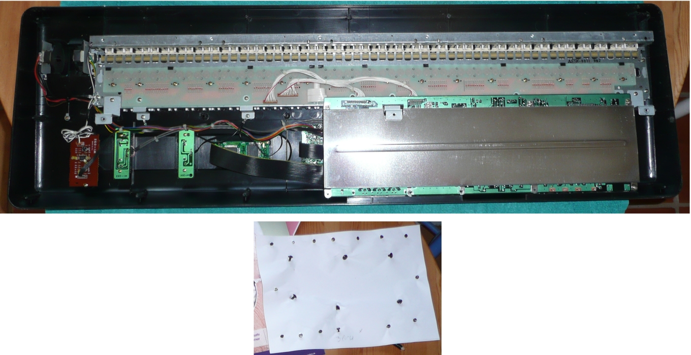
What you see wiith the base removed . Note the screws stored in the sheet of paper.
|
As you can see there is a reasonable amount of empty space inside – it’s a pity Kawai didn’t use this for an integrated mains power supply.
So on to the next stage – removing the metal shield from the circuit board. This is held on with 9 screws – 5 along the back and 4 along the middle. In fact only one of the screws along the back is internal, 4 of them double up as the case screws that have already been removed. So I removed the remaining 5 screws and pushed them in another piece of paper. I slid the metal shield towards the back of the keyboard and out from under the metal bracket. I thought the circuit board would be loose at this point but found it was still held in place by the two screws either side on the rear MIDI ports. So as before, these were removed and stowed in a sheet of paper et voila, the circuit board was loose. It was connected to other ‘things’ by a number of cables at one end – this allowed enough room for manoeuvre to pass the bracket through the big hole in the circuit board and then flip the board over and pivot it to the left.
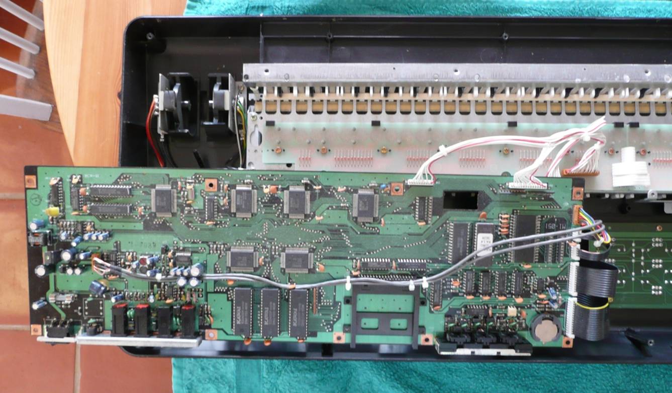
Revealing the circuit board holding the switches fixed to the top of the case.
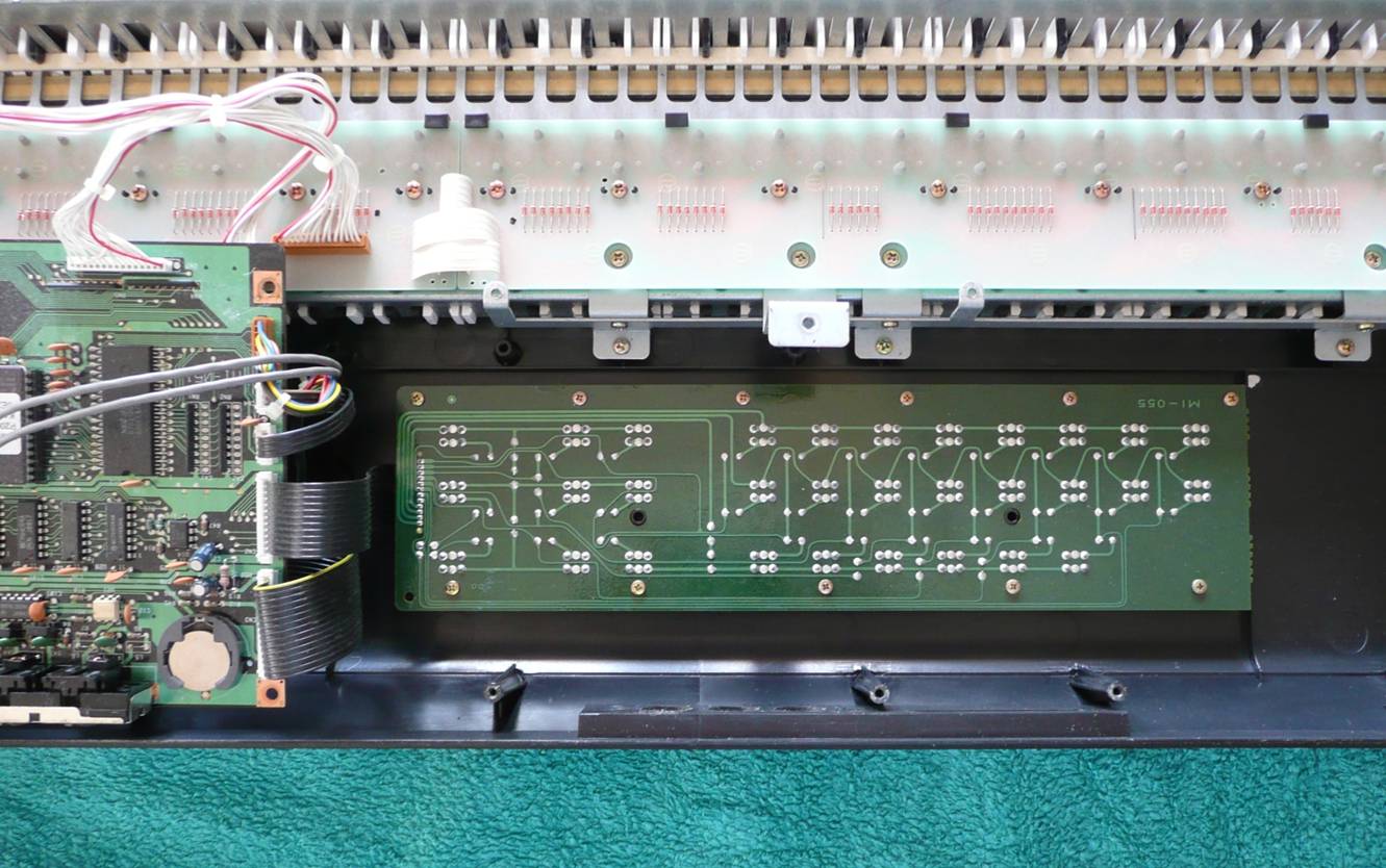
The board with the switches is held in place with 11 screws and connects to CN2 on the main circuit board with a ribbon cable. As before I removed the screws and anchored them into a sheet of paper and then looked to disconnect the ribbon cable. This cable is actually soldered to the switch board but can be disconnected at the main board end by lifting the plastic tabs at the ends of the socket which releases the cable.
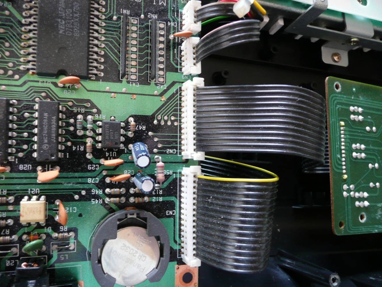
Here you can see connector CN2 with the locking tabs pulled up and releasing the end of the ribbon cable.
|
Also worth noting here is the backup battery for the memory. A simple CR2032 held in a holder which means that replacing the battery is really simple – no soldering involved.
I protected the end of the disconnected cable by wrapping paper around it and holding that in place with a sticky label.
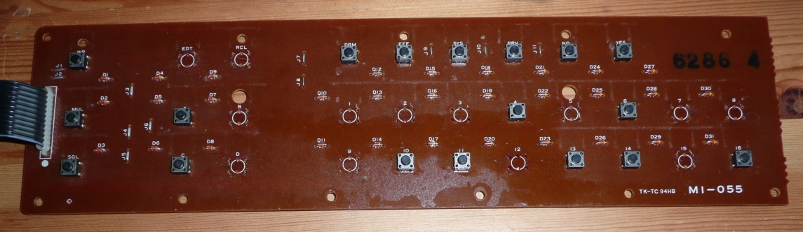
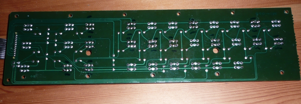
So now the button circuit board is free and can be lifted safely from the case.
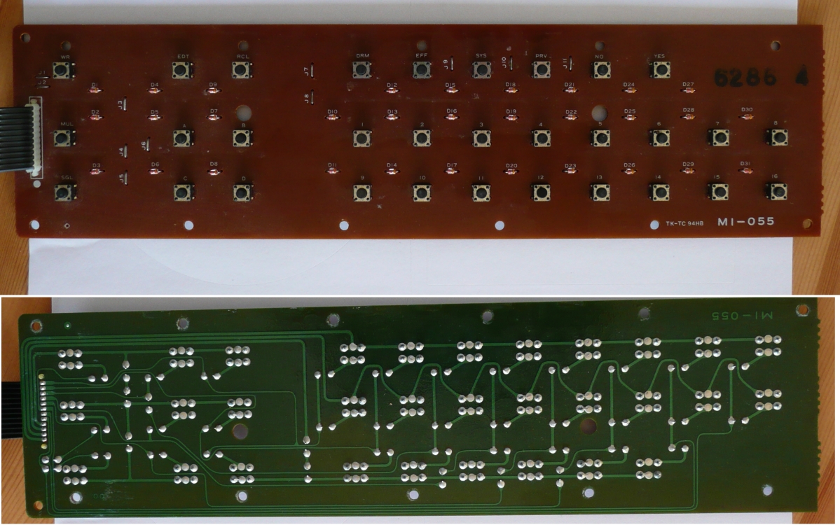
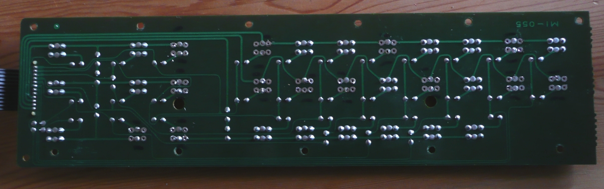
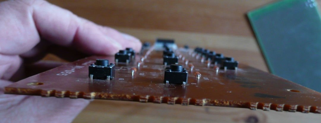
The board only has 'tact' button switches and diodes - and plenty of working space.
|
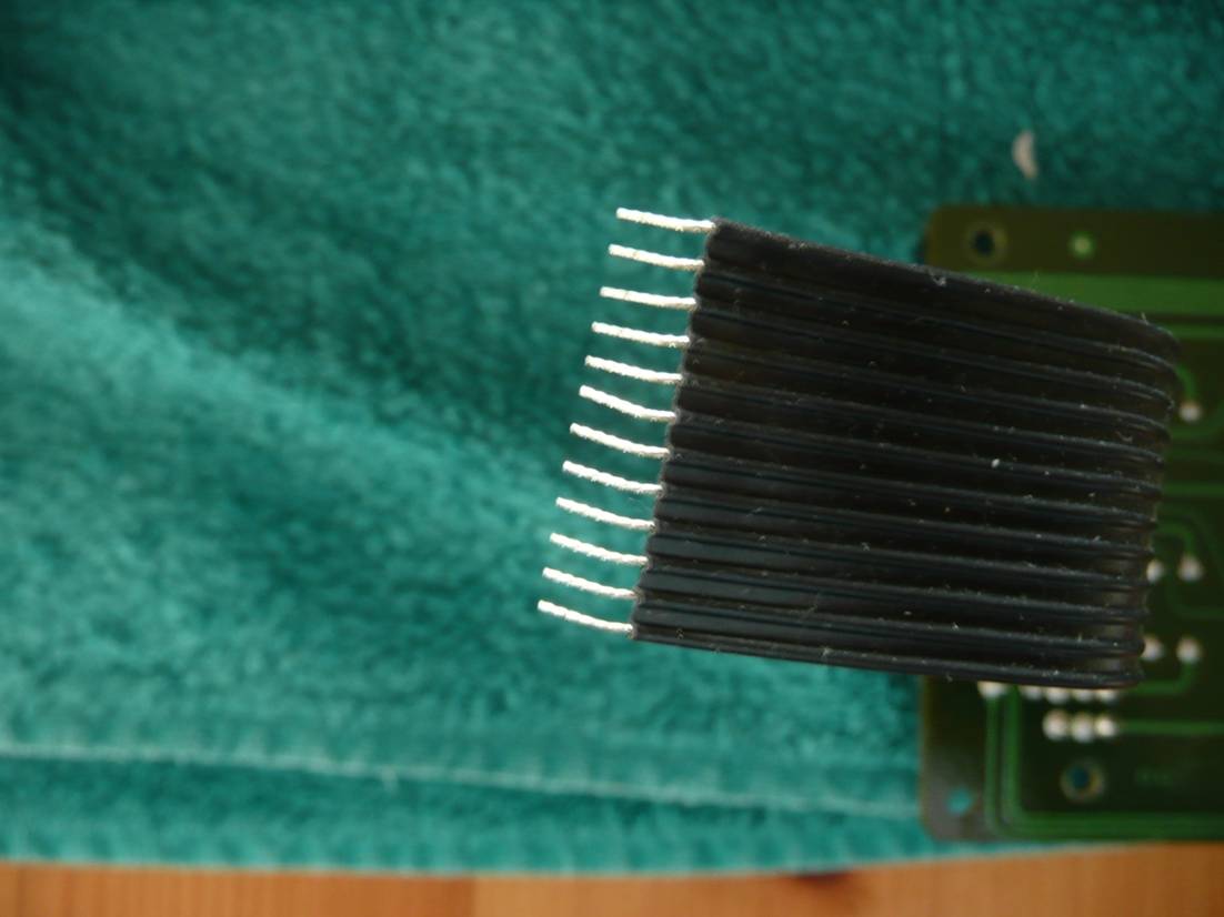
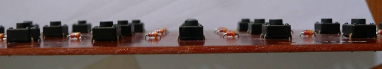
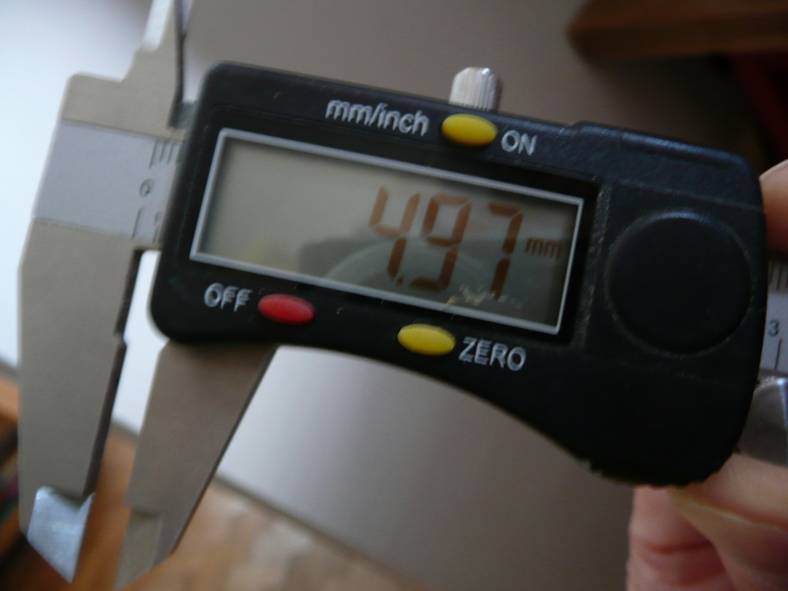
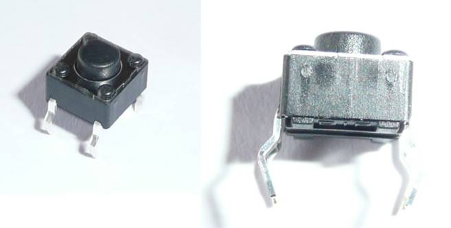
A quick look at the buttons shows them to be standard ‘tactical switches’. They are the standard 6mm x 6mm ‘through the board’ switches with 4 soldered connectors each. However, it’s important to get replacements that are the correct height and searching on the internet shows a huge variety of heights available. To be sure of the right size I used my micrometer gauge which showed them to be 5mm high.
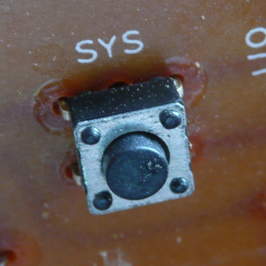
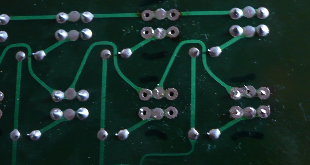
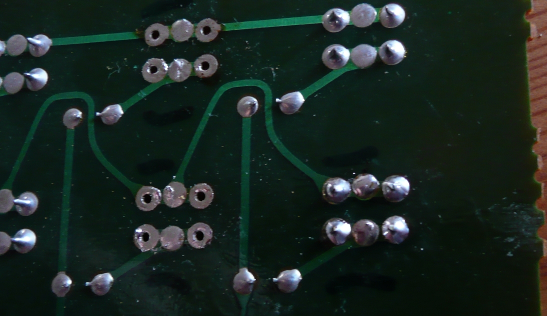
One thing that struck me as a bit surprising is that there are six soldered pads for each switch even though only 4 of them are actually used. A quick close up look shows that there are actually 6 holes available for connecting each switch allowing for the use of tact switches that have just two central connecting tags. Basically Kawai could use whatever standard components were readily available at the time of manufacture
I did a fair bit of searching to find suitable switches. Although I found several possibilities in most cases there were a number of negative factors:- horrendously expensive shipping, high minimum order value, expensive individual cost. Suffice it to say I ended up buying from Ebay a pack of 50 for about £7.50 including VAT and delivery.
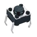
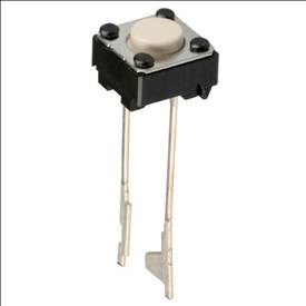
The picture on the left is the type of switch originally installed and the replacements I have ordered. The switch on the right could also be used.
|
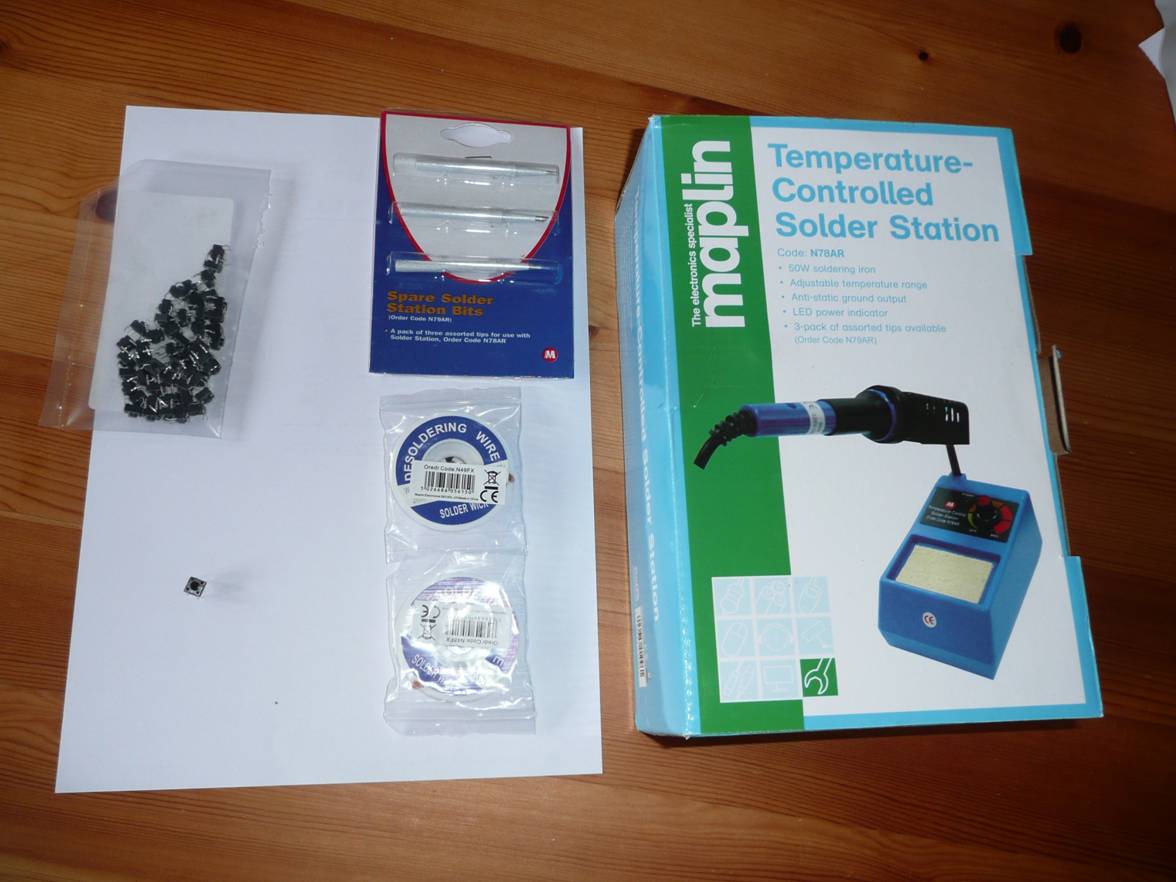
So now I have to wait to receive delivery of a soldering iron and desoldering braid. It’s years since I’ve done any soldering so I’ll have to get a bit of practice before I try on the actual circuit board. Not having a reasonable soldering iron available I was lucky to find a variable temperature soldering iron on special offer from Maplins with a 70% discount (only £9.99).
One of my concerns was to check the electrolytic capacitors on the circuit board as other old synths have been reported as suffered from failing and leaking capacitors that have corroded the tracks on the circuit board, but as far as I can see my K4 capacitors all look fine.
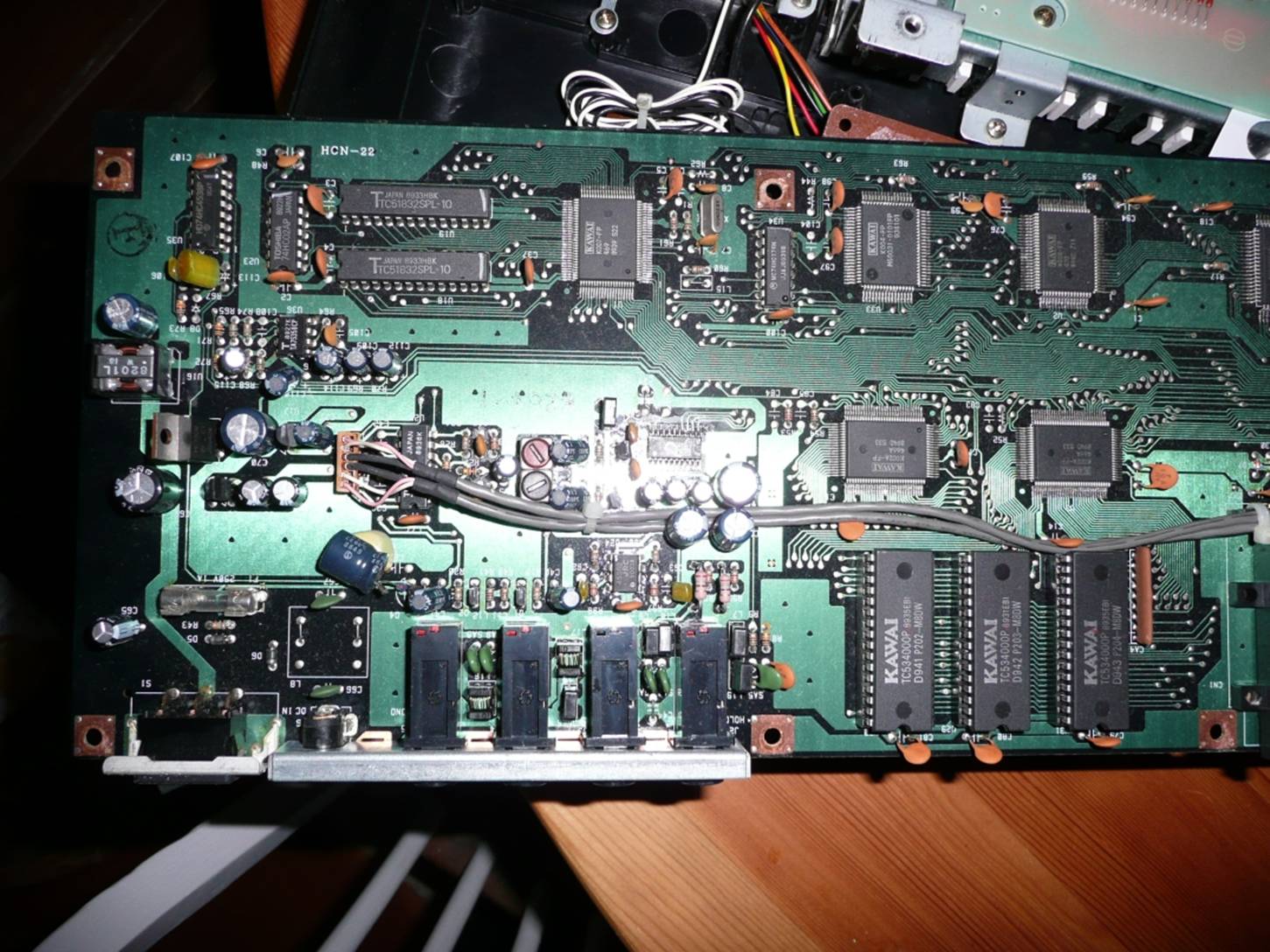
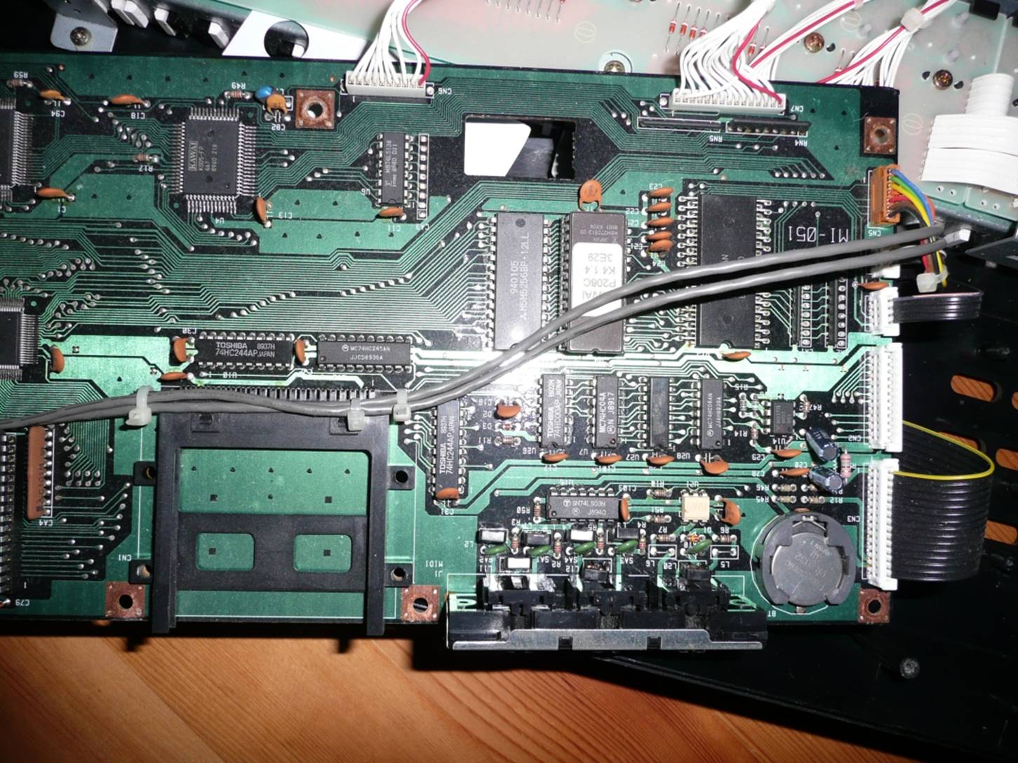
On the main board it appears that the Operating System chip and the 3 sample chips are actually in chip sockets to allow straightforward replacement for updates. So for reference here are the two halves of the main board.
Well the soldering iron arrived this morning, so I now need to find something to practice the desoldering on. Hopefully the switches will be here soon – I’ve had notification that they’ve been posted today.
Another delivery and I’ve got all the stuff I need to proceed
These are the actual switches delivered.
|
Another decision I have to make is whether to replace all the switches or just those giving problems. I spent some time before dismantling the synth testing the switches to make sure I knew which were a problem. In the end I decided to change only the 13 that showed any signs of being intermittant. I drew a plan of the switch layout to show which need to be changed and then used this to actually mark the ones to be changed on the circuit board with a marker pen. It seems to make sense to change any of the switches that show any signs of intermittant or poor contact, rather than make do with just changing the really bad ones and then have to dismantle it all again in the near future.
So I now just need to find an old unimportant circuit board to practice on and then I can get down to the real job.
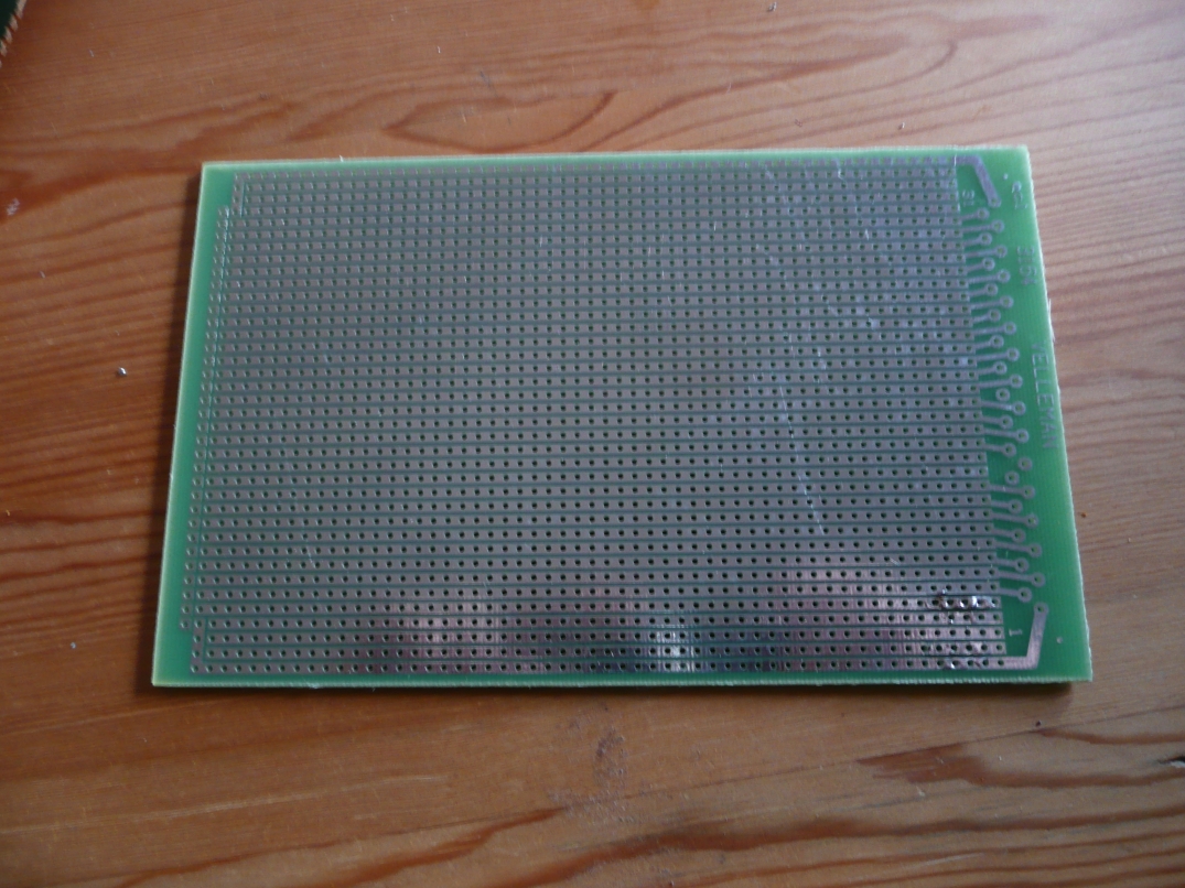
I've obtained a piece of Veroboard circuit prototyping board and tried soldering a switch into place and then removed the solder with desoldering braid, which all seems to have gone OK
So now on to the real job in hand and as is often the case things don't work as expected. First the solder braid did not manage to remove all the solder and the switches were still held in place with remnants of solder. I then tried my little vacuum solder sucker but that also failed to release the switches. So I then move to the brute force method and using side cutters I cut through the four soldered legs of each faulty switch on the upper side of the circuit board - this let me remove the body of the faulty switches but left the soldered legs in place. I then used the soldering iron with the desoldering braid on the lower surface which removed most of the solder and freed the soldered legs. In some cases I needed to hold the top of the remaining leg in a pair of pliers while heating the lower surface in order to remove them.
Finally I had removed all the parts of the faulty switches and excess solder. It is fortunate the circuit board is very simple with the circuit tracks just on the lower surface, but despite this I was concerned not to overheat the board as it is easy to damage the tracks and either cause them to fracture or peel off of the board.
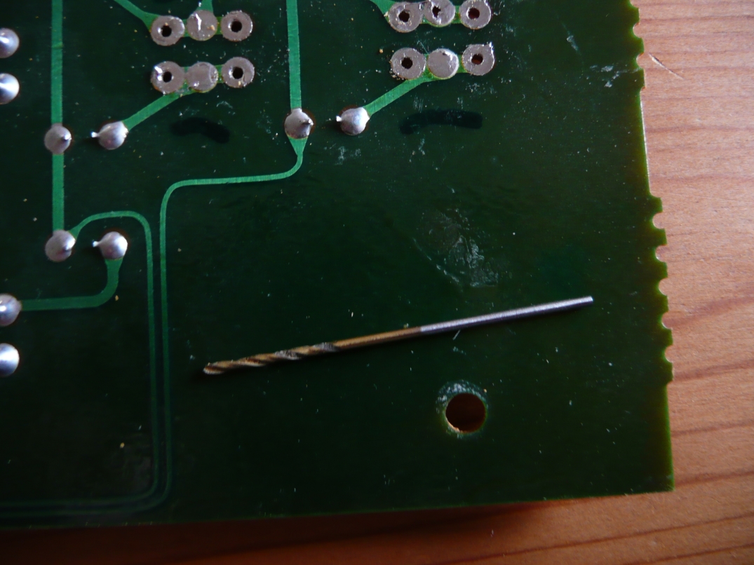
To make sure that the holes were clear and the legs of the new switches would fit in place without a problem I use a 1mm drill rotated between finger and thumb.
So now on to inserting the new switches ensuring the bottom of the switches is flat against the board.
Solder pins of new switch show through the holes on the board
After quick application of solder the first replacement switch is in place
Then all the rest of the switches inserted and soldered and the replacement is completed.
So a quick check to make sure it all looks OK and then on to putting it all back together. First connecting the ribbon cable making sure the end is fully in the socket which needed a bit of a push and then pushing down the locking clip. I had actually removed the button tops to clean them, so I replaced them in the correct position and then screwed the button board back in place. Then I flipped over the main circuit board, replaced the metal shield and replaced the screws including those in the rear by the midi sockets. Finally the base went back into place - note that the screws along the back are longer than those along the front.
Finally power on and it still works. Then testing each button in turn I'm pleased to find they all work. Mind you I wonder if I should have replaced all of them as a couple still needed more than one press.
Well, it's now a couple of weeks since I changed the switches and only one (the SYS) button actually sometimes needs more than one press before it works, so when I've got an hour to spare I'll open it up again and change it.
Another point is the soldering and desoldering. I had 3 different desoldering options.
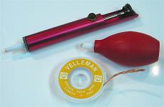
1. The desoldering braid that was best for the final cleaning of the solder off of the circuit board. Using a flat soldering bit worked best but the braid has to be removed from the circuit board as soon as the soldering iron is removed
2. The rubber bulb sucker that is squeezed and then released to suck up the melted solder - this was not very good
3, The sprung desolder tool where a button is pressed and the spring loaded plunger is rapidly released and sucks up the liquid solder - this sometimes neede to be done 2 or 3 times but worked well.
I was concerned to not overheat the circuit board so wanted to do the soldering and desoldering as quickly as possible.
As a result of all this I currently (Aug 2010) have a number of spare tact switcheswhich I am happy to send to anybody that needs to repair their K4 or K4r. Email me if you are interested - I check this mailbox weekly.